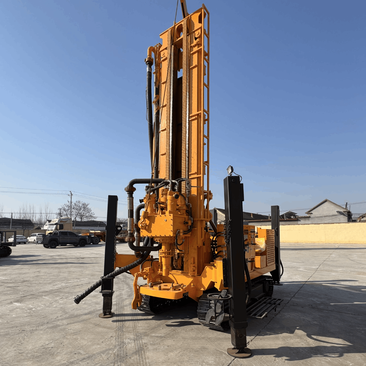
Safety Operation Guide for Water Well Drills: Five Golden Rules from Transportation to Maintenance
1. The “Three-Balance Rule” in the Equipment Transportation Stage
Center of Gravity Balance Management
When the new water well drill is being transferred, it is necessary to follow the triangular balance principle of “terrain – equipment – vehicle”. When transporting on mountain roads, it is recommended to control the inclination angle of the mast within 15°, and retract the crawler to the standard width of 2.8 Mètres. In particular, when the transport vehicle enters sandy roads, the pressure value of the hydraulic support system must be checked in advance to ensure it remains within the safe range of 18 – 22 MPa.
Solutions for Special Road Conditions
- When encountering narrow roads less than 6 meters wide, the “lower – mast and slow – driving” strategy should be adopted, reducing the mast height to below 3 Mètres.
- When passing slopes with an inclination of over 15°, the “reverse – climbing” technique should be used, keeping the engine speed between 1800 – 2000 rpm.
- In water – logged sections, a Φ200mm drill pipe must be used as a pathfinder. If the water depth exceeds one – third of the crawler height, the vehicle should stop moving forward.
2. Safety Protection System at the Construction Site
Standard for Establishing the Early – Warning System
A three – level warning should be set up within a 30 – meter operating radius:
- Reflective warning posts should be placed at the outer perimeter 50 meters away (with a spacing of no more than 5 Mètres).
- An audible and visual alarm device should be installed in the core operating area.
- The drill rig operator’s console should be equipped with an emergency brake button linkage system.
Management of Drilling Forbidden Zones
Strictly implement the “Three – No – Drilling” principle:
- Drilling is prohibited within 3 meters of underground pipelines.
- Drilling operations should be suspended within a 5 – meter radius of load – bearing walls.
- When encountering an unknown hard layer, a geological radar scan must be conducted first.
3. Maintenance Specifications for the Hydraulic System
Four – Level Cooling and Maintenance Process
Establish standardized operations for hydraulic system maintenance:
- After stopping the machine, wait for the hydraulic oil temperature to drop below 45°C (about 90 minutes of natural cooling is required).
- Use the hierarchical pressure – relief method: first release the pressure of the main pump (> 25 MPa), and then deal with the actuators.
- When replacing the main winch brake, a “double – insurance” must be hung: mechanical brake + hydraulic locking.
- Pay attention to the rotation direction mark when installing the wire rope. A right – hand – lay rope should be used with an anti – rotation guide wheel.
4. Emergency Handling Plan for Faults
Establish a “Three – Level Response Mechanism”:
- Primary Response: The operator should immediately activate the emergency stop device to cut off the power output.
- Intermediate Disposal: The technician should use an infrared thermal imager to detect the fault point and record the abnormal temperature range.
- Expert Support: In case of continuous high temperature (> 80°C) or abnormal pressure (exceeding the standard value by 30%), the manufacturer’s engineer must be contacted.
5. Personnel Safety Protection System
Implement a “Double – Barrier” Protection:
- Physical Barrier: Install a mesh protective cover (with a mesh size of ≤ 5mm) on rotating parts.
- Intelligent Barrier: Equip UWB positioning bracelets. When a person enters a dangerous area, the equipment will automatically slow down. Professional Suggestion: It is recommended to conduct “simulated fault drills” quarterly, focusing on the handling of common emergencies such as hydraulic pipe bursts (with an incidence rate of 12%) and wire rope breakages (with an incidence rate of 8%). The emergency toolbox should be equipped with professional equipment such as high – temperature – resistant gloves (able to withstand 300°C) and hydraulic pipe quick – plugging devices.
 Foreuse Bangxin
